Design Research ● Product Design
A great building must begin with the unmeasurable, must go through measurable means when it is being designed and in the end must be unmeasurable. — Louis Kahn
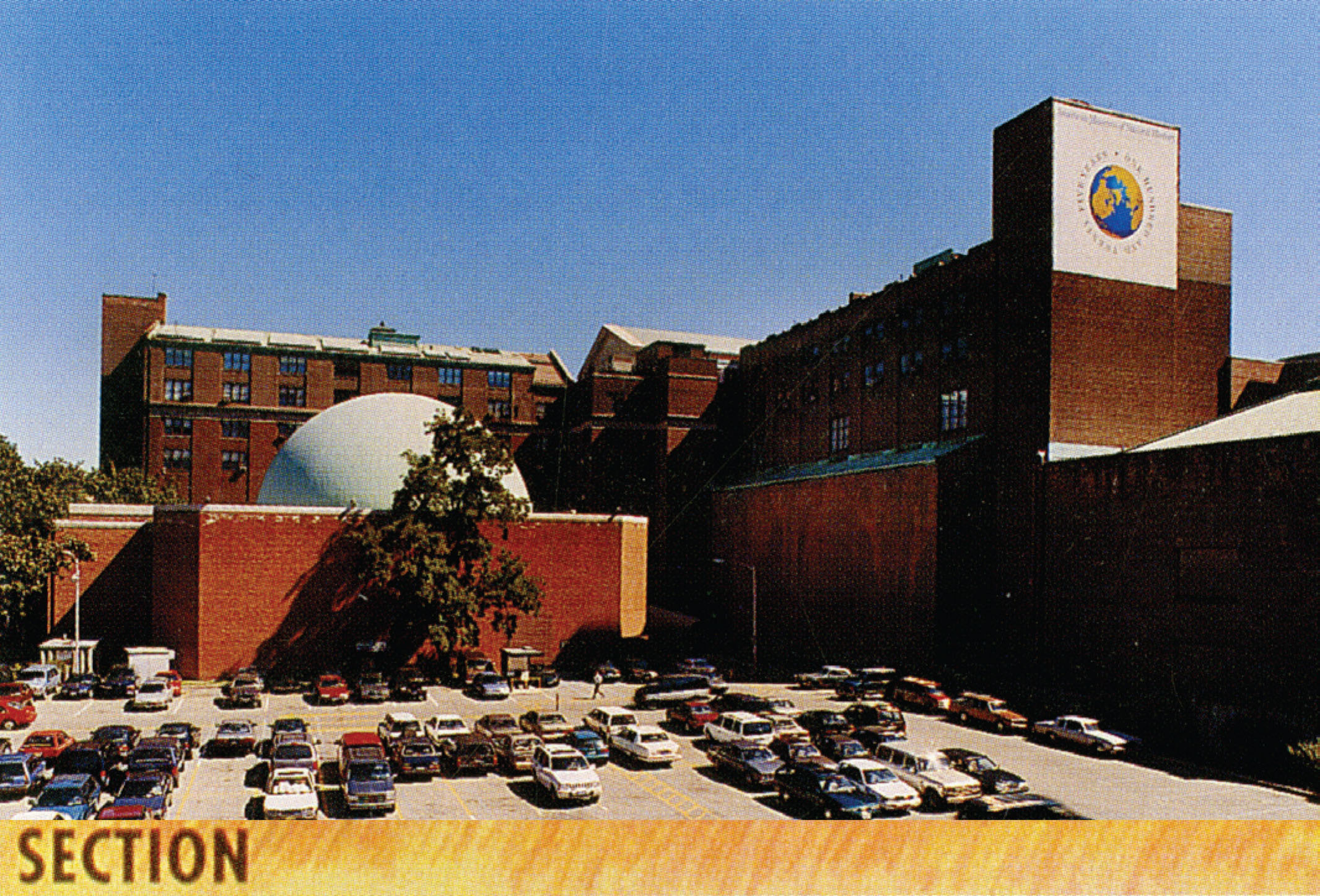
The Rose Center for Earth and Space emerged from a more modest initial plan to renovate the old Hayden Planetarium, both to house a new exhibit, and to enable more intuitive circulation through the greater museum complex. Polshek Partnership Architects were initially involved as architectural consultants to the exhibit design team, but upon touring the premises with the museum administration, it was agreed that a more ambitious scheme would enable a more contemporary and powerful identity for the planetarium, reflecting the great advances in the field of astronomy since the original Hayden’s completion in 1936.
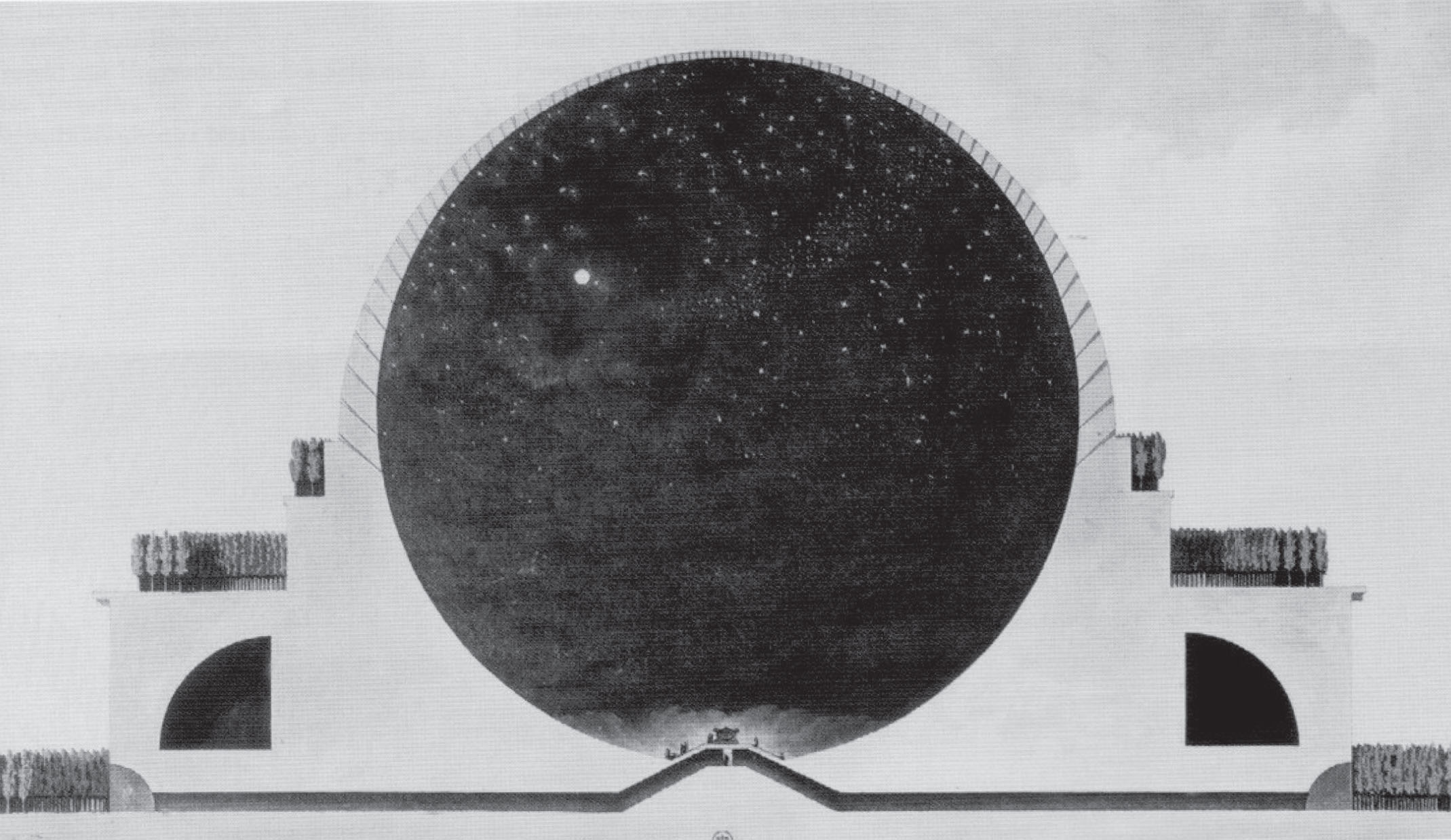
Taking Étienne-Louis Boullée’s unrealized Cenotaph for Isaac Newton (1784) as inspiration, Polshek proposed the Hayden’s hemispherical dome be completed by suspending the lower spherical portion from the existing ring of support columns. When it became clear that the existing structure could not accommodate the desired expansions to program and circulation, the museum appealed to the New York City Landmarks Preservation Commission for permission to demolish, which was granted in November 1995.
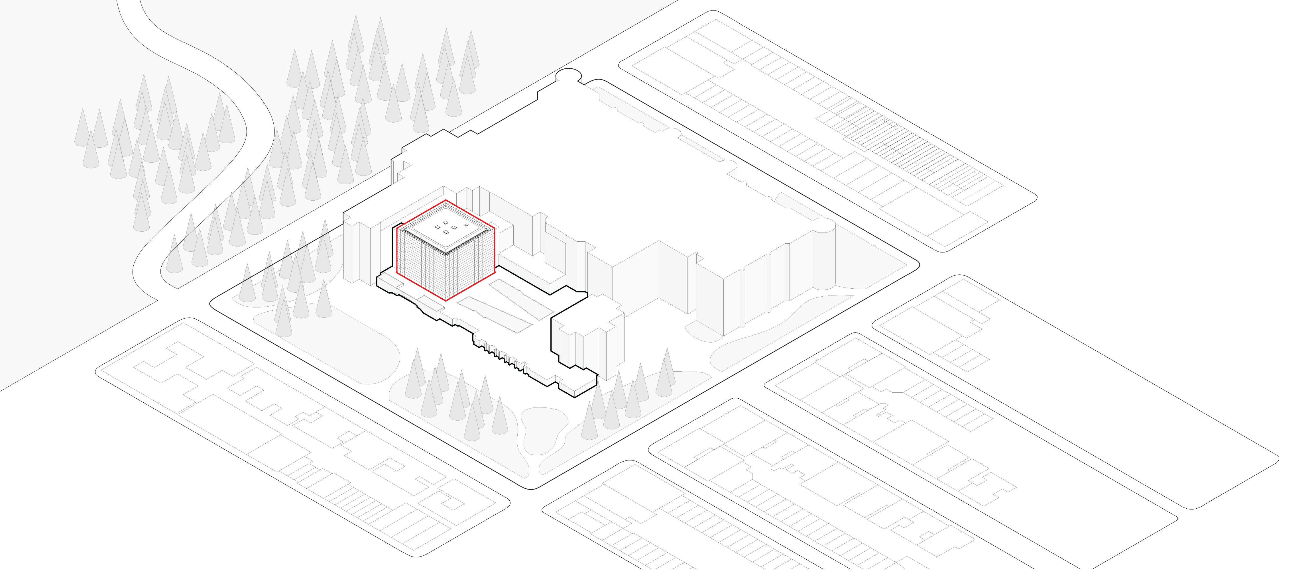
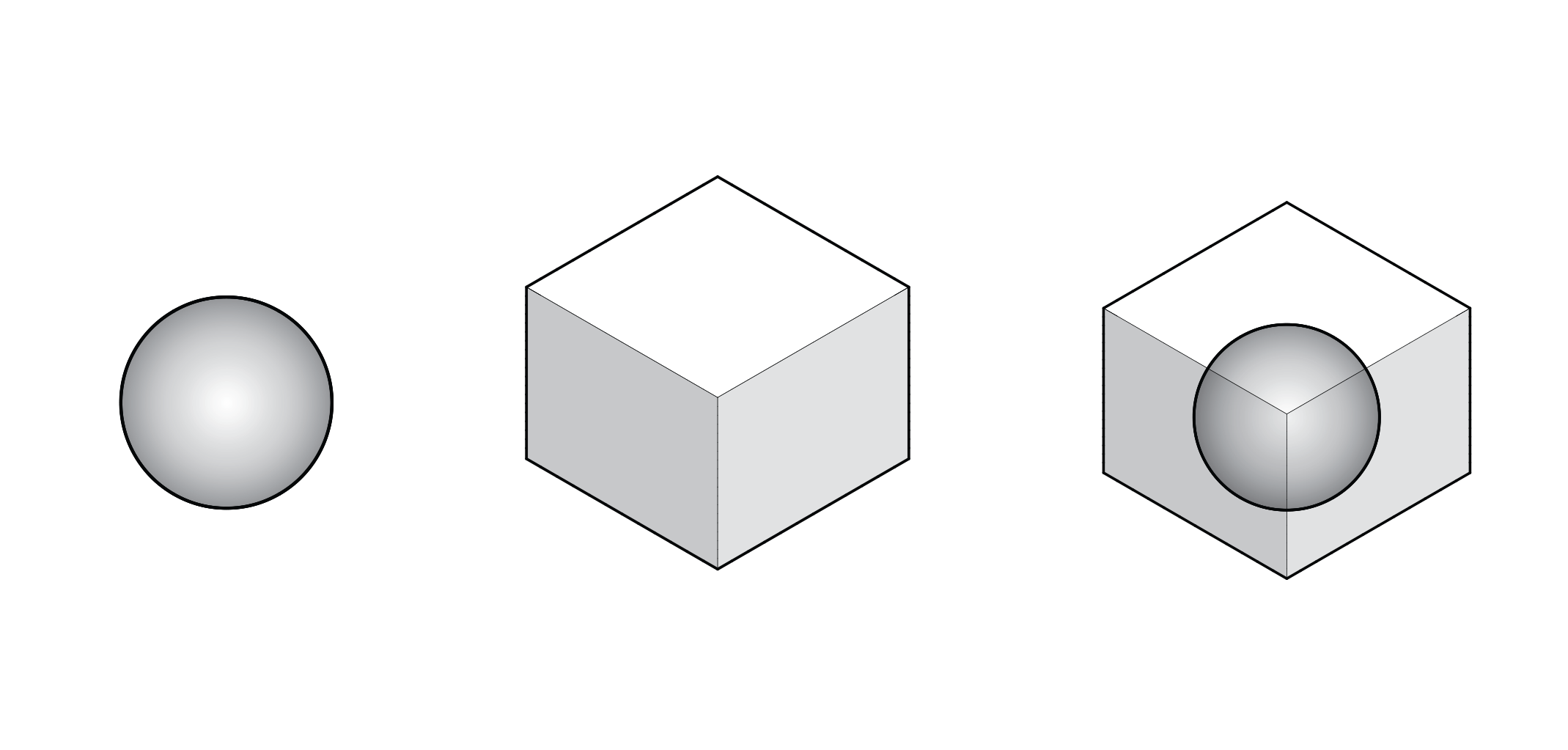
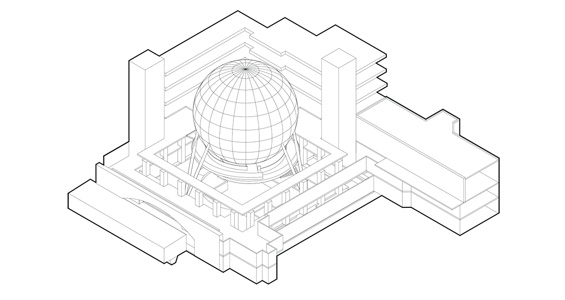
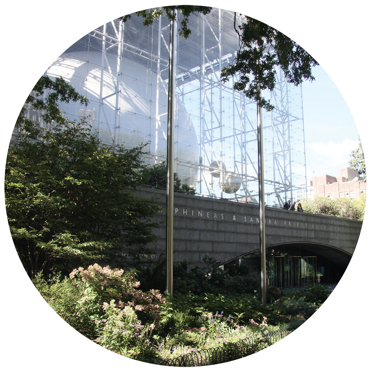
Having secured a relative tabula rasa, Polshek was free to imagine a concept that both fulfilled contemporary institutional needs, and visualized the enormity of the concepts that the planetarium was intended to convey. Boullée’s sphere remained a key conceptual and aesthetic driver, leading to a pure geometric vision: a perfect sphere, levitating in the midst of a nearly invisible cubic enclosure, visible day and night. While the key triumphs of the realized building – the unprecedented transparency and visual lightness of its curtain wall, and the structural ingenuity needed to elevate its spherical theater – produced a budget in excess of $210 million, they resulted directly from efforts to bring this deceptively simple parti to life.
The Rose Center for Earth and Space opened its doors in 2000, inaugurating the new millennium with an architectural icon that both gives form to and broadcasts a powerful new vision for this key New York institution.
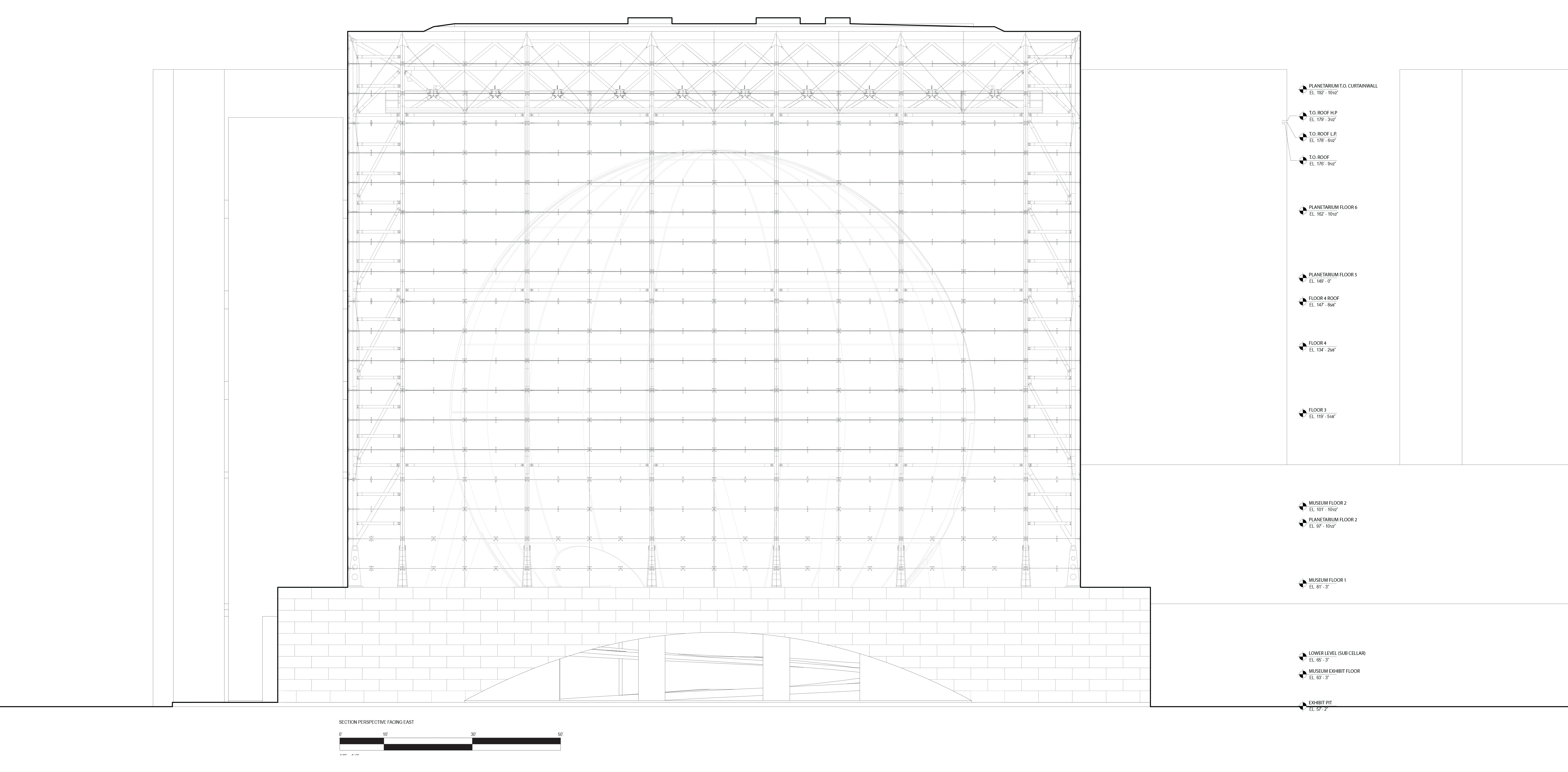
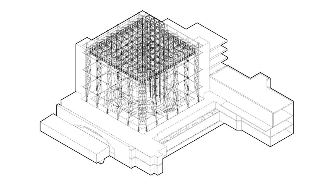
The Rose Center consists of several structural systems: the curtain wall, the rigid frame, the central sphere, the floor system, shear wall system, and the foundation.
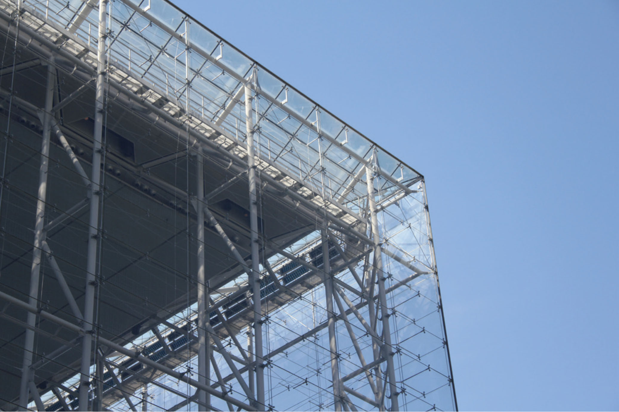
The curtain wall consists of two facades, each containing 228 vertical panels of single pane glass, supported by a total of 1,400 steel spider joints.
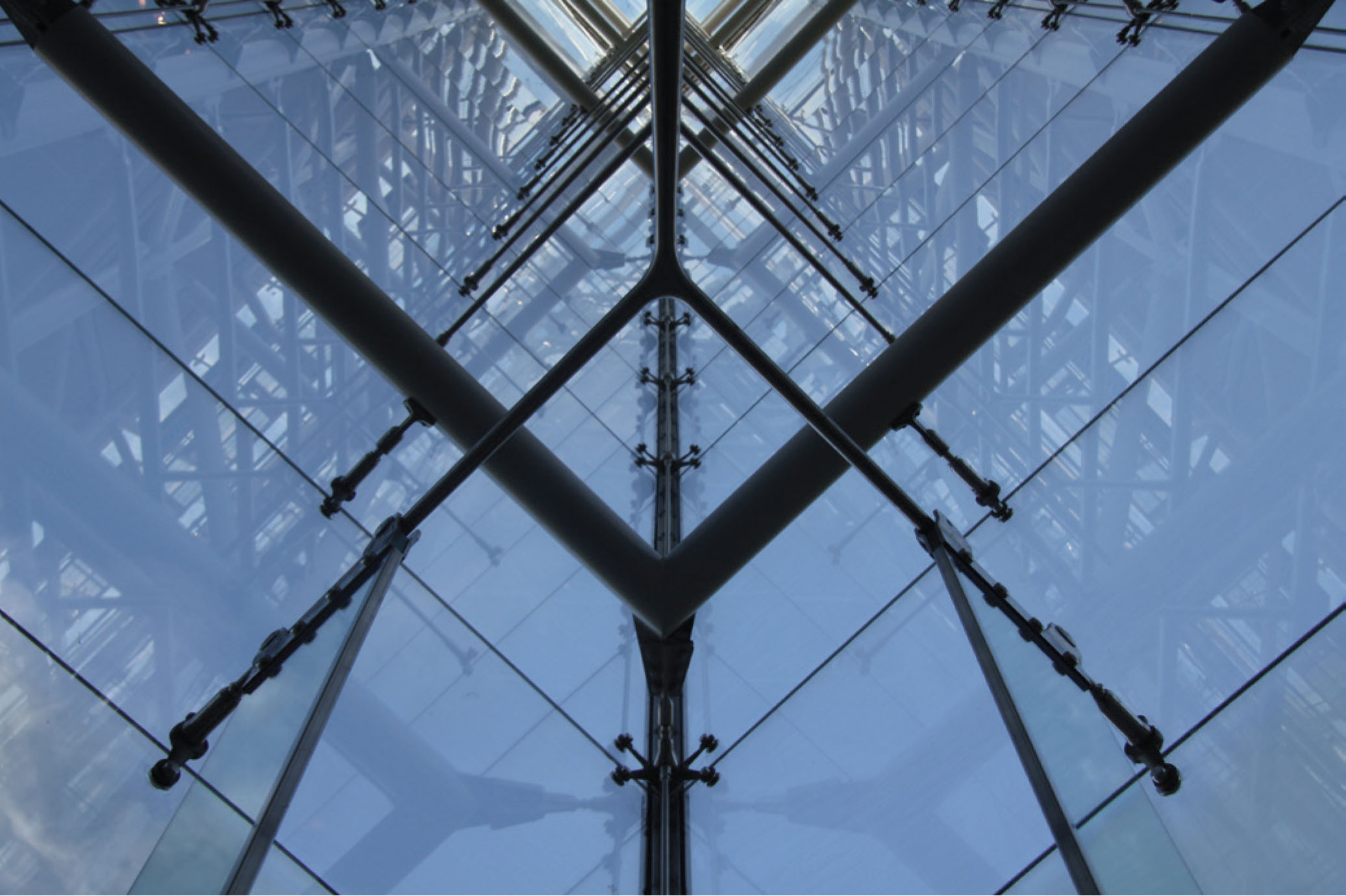
Each pane of glass is supported at the top by two spider connections. The bottom two spider joints do not support the glass, which is in tension, but rather stabilize the pane. The spider joints are connected, supported, and held in place with post-tensioned steel cables. Central spider joints between bays additionally have a steel queen post connecting it to the rigid frame beyond.
The rigid frame consists of a series of six two-point arches in the North-South and East-West direction. This intersection of two-point arches creates rigidity, resisting rotation. Each two-point arch consists of two hollow-steel tube vertical trusses and one horizontal roof truss consisting of steel sections. The vertical trusses are bolted to the roof trusses, creating a rigid connection, and connect at their base with a pin connection. Rigid connections are susceptible to bending and hinge connections are susceptible to rotation. However, the structure is able to resist these reactions through its rigidity. This rigidity is achieved through the perpendicular arrangement of two-point arches. In effect, all reactions are cancelled out by its perpendicular counterpart, and the structure is able to resist these reactions. Thus, the pin connections are an architectural expression of a machine aesthetic and lightness, but do not function as the structure may suggest. They are rotational joints where no rotation may occur.
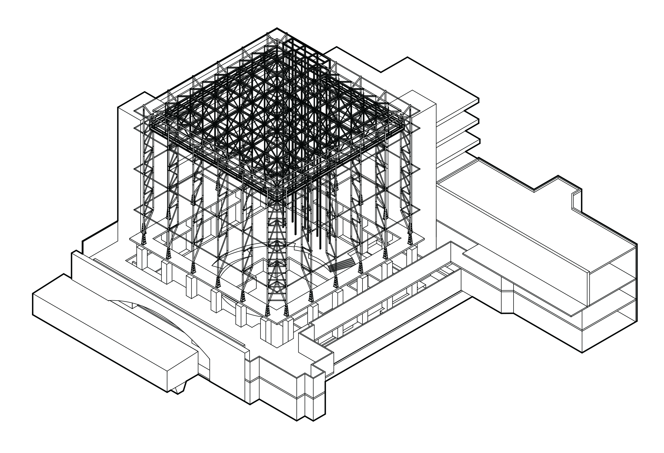
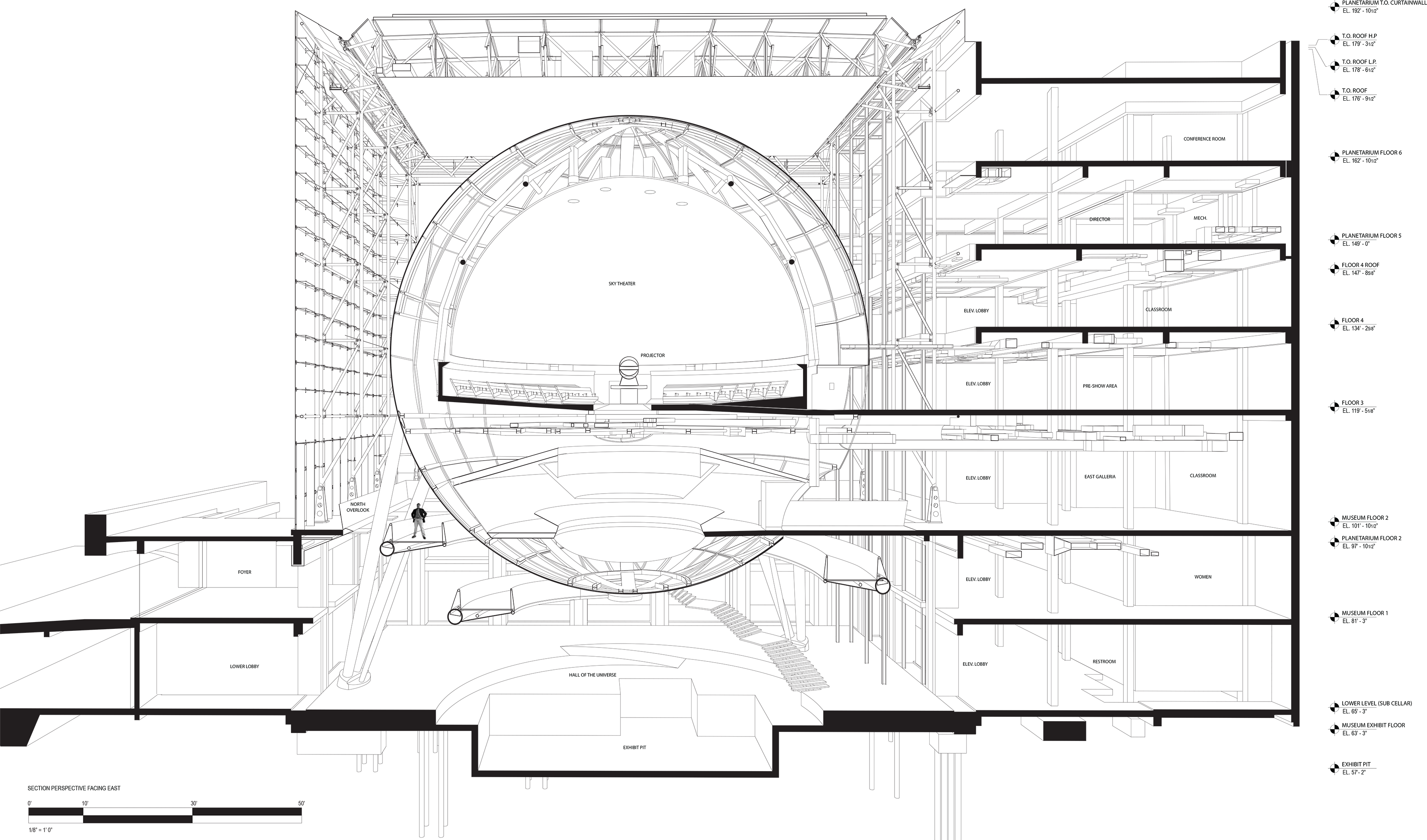
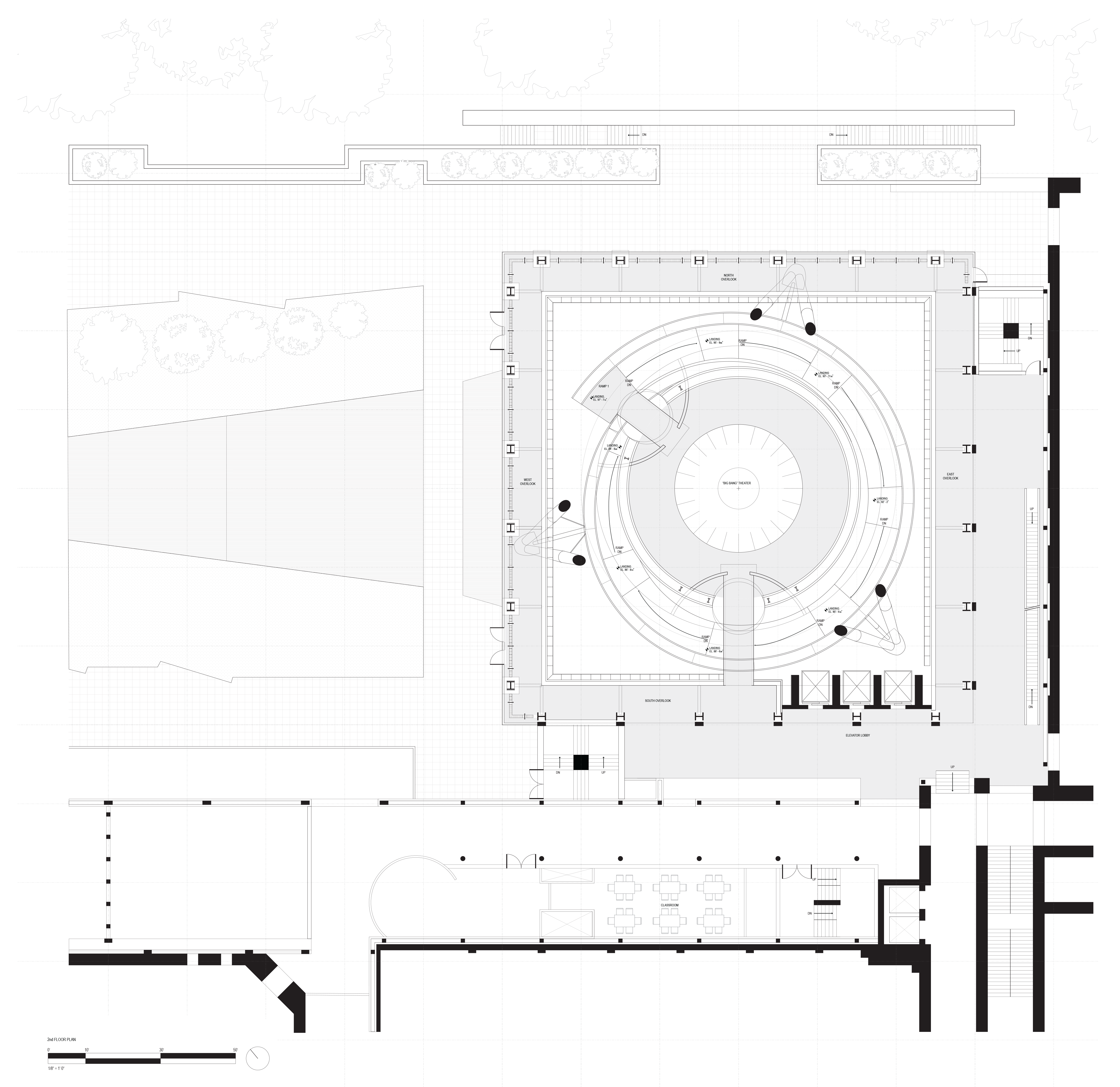
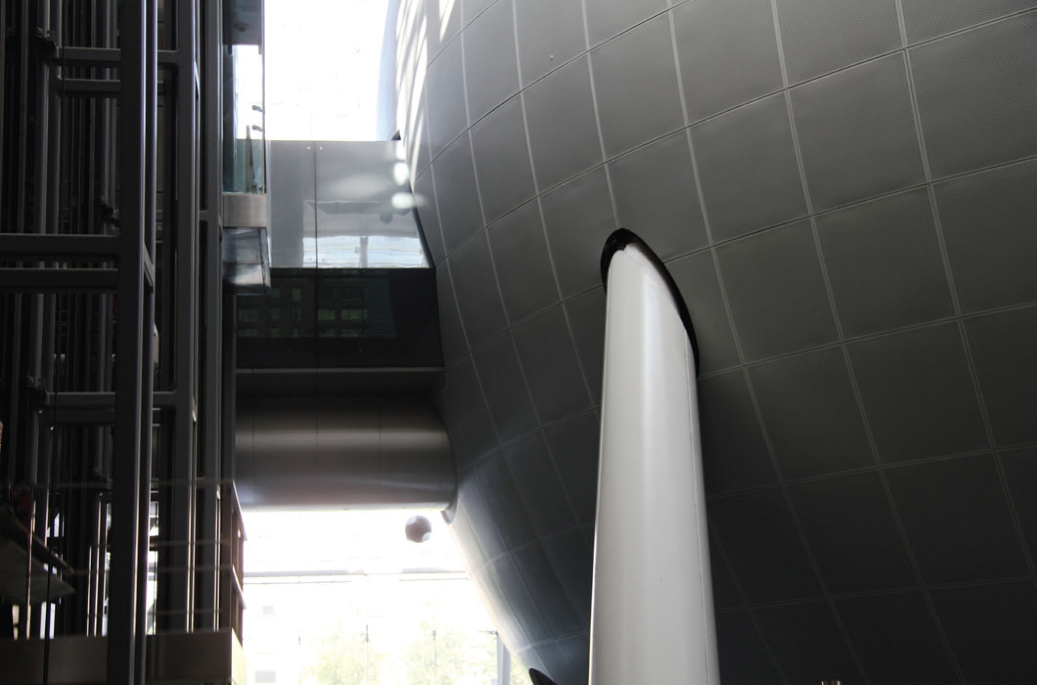
The structure of the sphere – 87 feet in diameter, and twelve feet taller than the original Hayden dome – is composed of curved steel ribs, ten-inches in depth, with a twelve-foot-deep circular truss at the almost four million pounds. Numerous structural concepts were explored (suspending it from the ceiling, cantilevering it from the walls, a single central support) before it was decided that the sphere would be elevated on a “tripod” consisting of three pairs of hollow, tapered steel columns. These are arranged in such a way that only one set of columns is visible from any given vantage point, almost as if the columns were leaning on the sphere rather than supporting it, thus reinforcing the impression of levitation. The sphere is clad in perforated aluminum panels that lend it the pure geometric character the architect desired, while preventing sound and light from the enclosed theaters from bleeding into the Hall of the Universe.
The floor system consists of a concrete slab and functions as a diaphragm around the entire cube, acting in both lateral directions. The shear walls beneath the steel trusses function to resist lateral wind loads. Finally, the foundation of the Rose Center is primarily the existing foundation from the previous planetarium. The choice to reuse the existing concrete piles, while creating an unconventional foundation plan, was extremely economical.

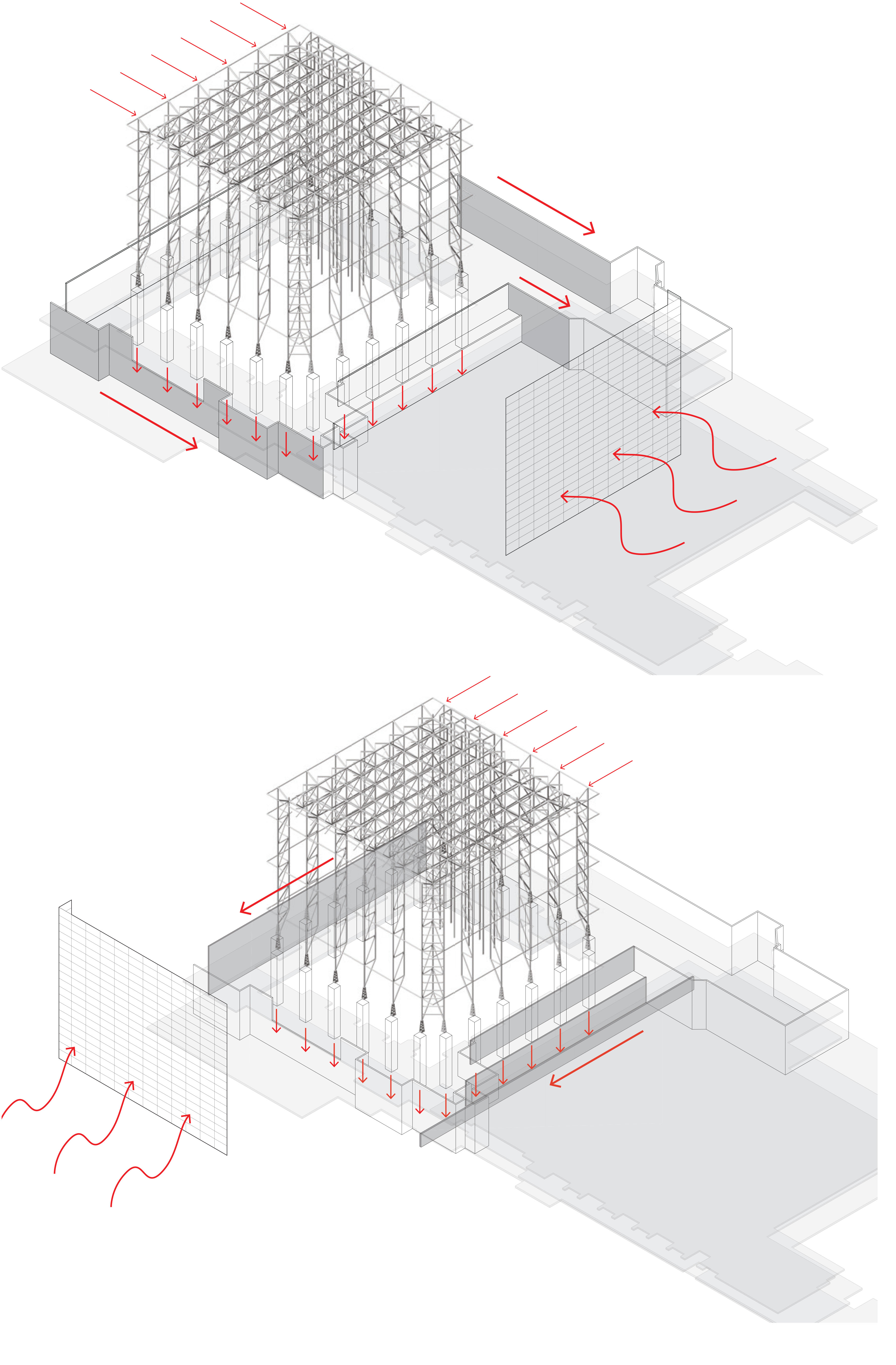
In the Rose Center, the structural systems work together to transfer and resist gravity and wind loads, which are all resolved in the foundation. First, when wind either hits the glass, creating positive pressure, or runs by the glass facade, creating negative pressure, the load is absorbed by the enclosure system structure. The curtain wall transfers the load to the spider joints which are in turn supported by the post-tensioned cords and queen posts. This system of joints and cords act like beams spanning the distance of the panes of glass. The load is then transferred into the rigid frame, which transfers loads to the floor slab below. The concrete floor slab acts as a diaphragm, transferring lateral load to the perpendicular shear walls below. These shear walls, perpendicular to the force, directly resist the lateral load, transferring the load finally down to the foundation below where the load is fully resolved and the structure achieves equilibrium.
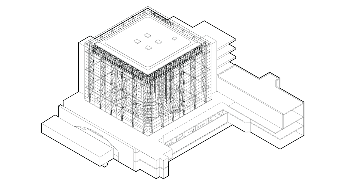
In order to achieve the architectural intention of the expression of pure geometry of the sphere, the cube must be as transparent as possible to expose a seemingly weightless sphere. The systems which allow this transparency are the facade enclosure, which is made up of single-pane monolithic glass panels, and the spider joints and cable system, which holds the curtain wall away from the structure. Also, the column trusses span a 21 foot bay, with only three horizontal bracing members. This allows maximum visibility through the enclosure and exterior skeleton into the interior sphere. Finally, the space frame roof connection to these trusses creates a rigid frame, eliminating the need for bulky reinforcement to stabilize the structure. Thus, the rigid frame is minimal and the glass enclosure is of maximum clarity in order to ensure the architectural intent.
Finally, the architectural intent is to realize the pure geometry without the distractions of extraneous structure or HVAC systems. The entire building employs systems and structures that are either hidden or minimized wherever possible. For example, the entire space frame of the roof system is hidden from view behind a paneled roof ceiling. So too, the HVAC in the Rose Center is hidden within the building, bringing fresh cooled or heated air to spaces without calling attention to the system itself. It is the architecture and the geometry that takes center stage at the Rose Center, and it is the systems and structure, though extremely designed and thoughtful, that serve to reveal the purity of the geometric forms.
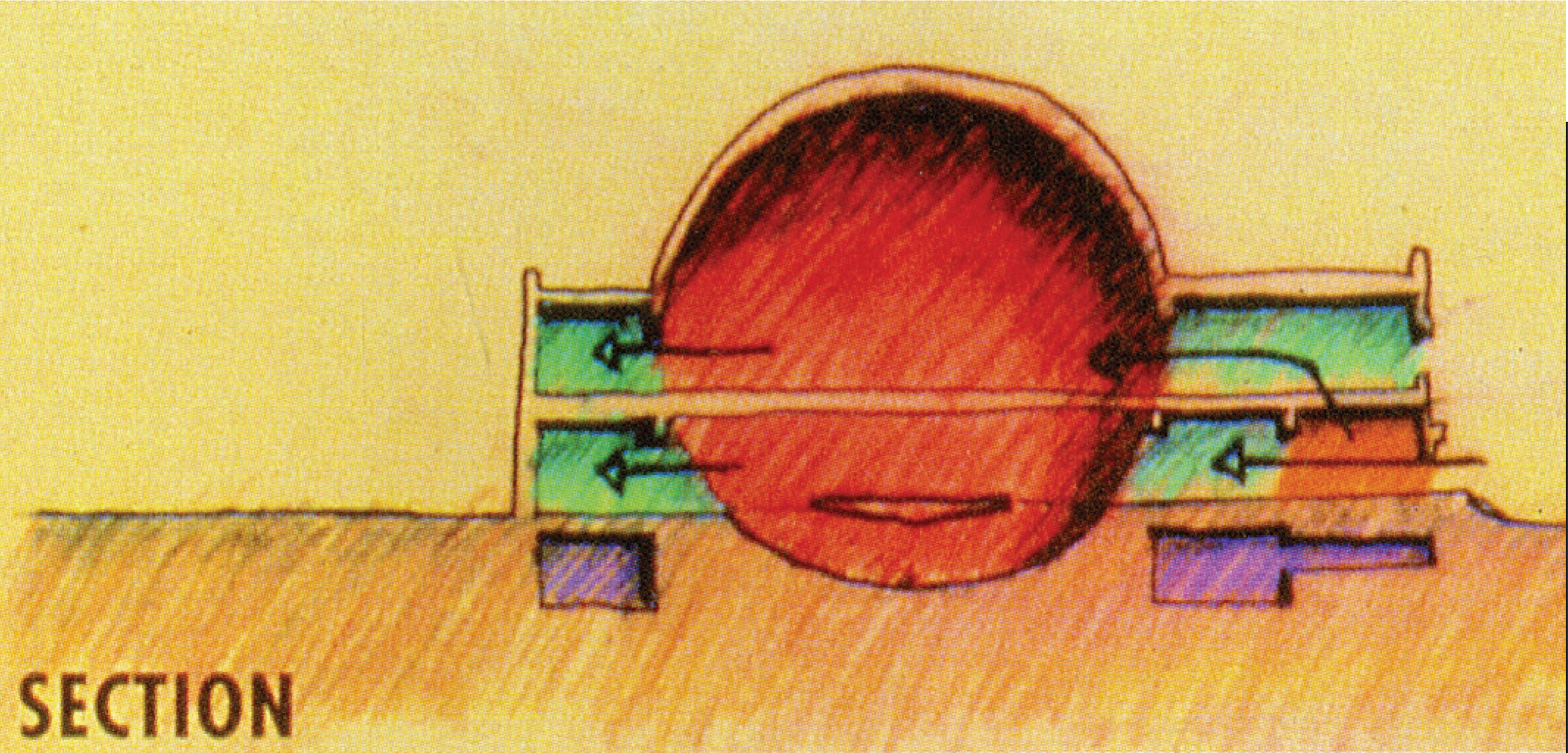
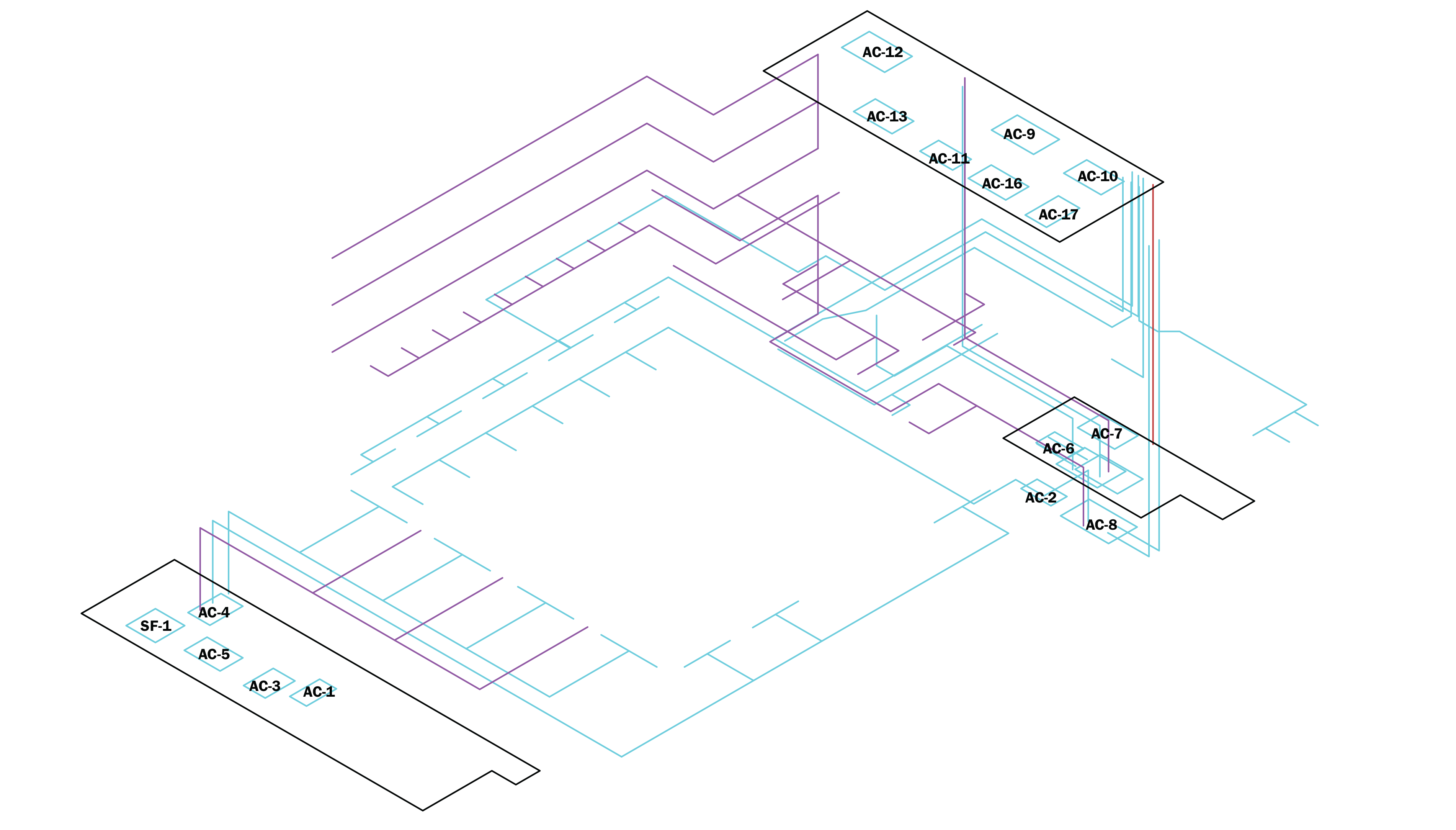
The HVAC is an extensive heating and cooling system, including 22 Air Conditioning Units, 4 Heating and Ventilation Units, stemming from 6 locations. Fresh air intake and exhaust occurs on the roof as well as at the ground level by the entrance, all of which is hidden by foliage. The conditioning zones are divided among the levels below grade, the walkway at grade, and the levels above that are primarily occupied on the south and east sides of the building. The second floor extends from the south and east sides of the building into the sphere across bridges, thus extending this particular zone of duct work. The ducts travel through the bridges into the crawl space of the sphere, serving the planetariums above and below it. Each level beyond has its own distributed supply and return duct system hidden in the slab. Architecturally, the supply and return ducts are only visible as thin slots that occur along the edges of the spaces or are hidden inside lighting coves. This allows for little to no visibility of the environmental systems.
Cool air is supplied and returned at each level through distributed ducts. On the levels above the second floor, air is supplied for the open space of the cube, serving the ramp, as well as the accompanying walkway at each level. Any air that passes into the open space of the glass cube that escapes individual levels of return ducts, is exhausted through 15’ long 1-½” wide architectural exhaust air slots located on the sixth floor.
In the sphere, cool air is supplied through floor grills at the center of the sphere and is returned through thin 2-½” return air slots located around the circumference of the space, mostly hidden behind the seating. The top of the dome is the location for not only return air ducts, but also the smoke exhaust collars that are used in order to evacuate the sphere in the event of a fire. These vents are located behind the perforated interior panels of the planetarium and are therefore unable to be seen. However, this location presents the problem of soundproofing, as this interior space is an event space, and are therefore lined with 1” thick acoustical lining.
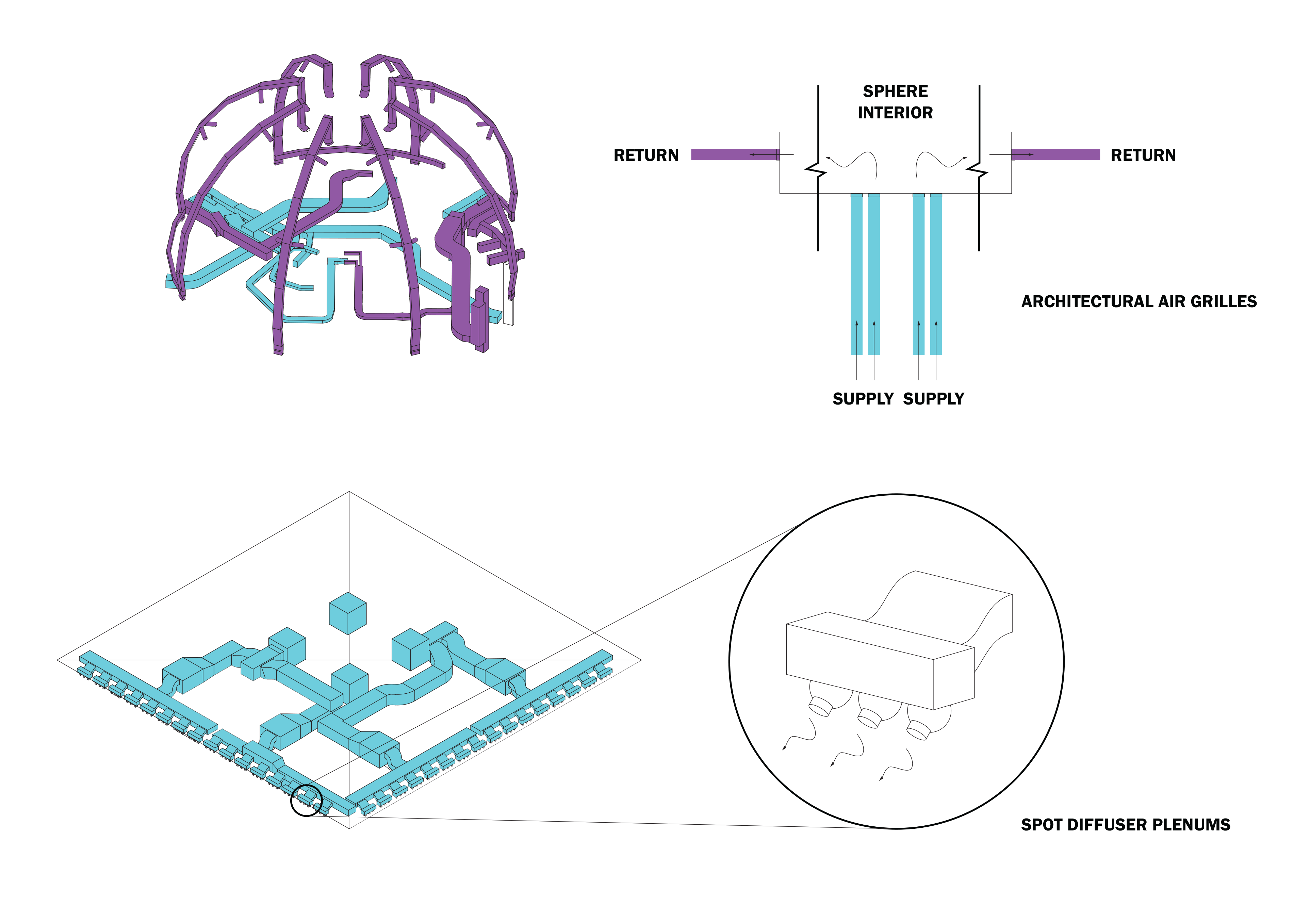
Since the Rose Center shares environmental conditioning with the existing museum, humidity is a key factor in its environmental controls. During the winter, the single pane glass on the facade is vulnerable to condensation and must be heated in order to maintain its architectural transparency. The Heating and Ventilation system for the facade is nested within the space frame of the roof of the cube and delivers heated fresh air onto the glass through a series of spot diffusers along the north and east sides of the facade. The heating system in the roof functions in conjunction with the heating system near the base of the glass. Since this area is occupied space, the air grills in the floor prevent the cool air draft from penetrating the walkway. This extraneous system could have been more efficient if the glass had been insulated, however this would have strayed from the original intent for the glass to be as consistent in transparency and color at all times of the day.
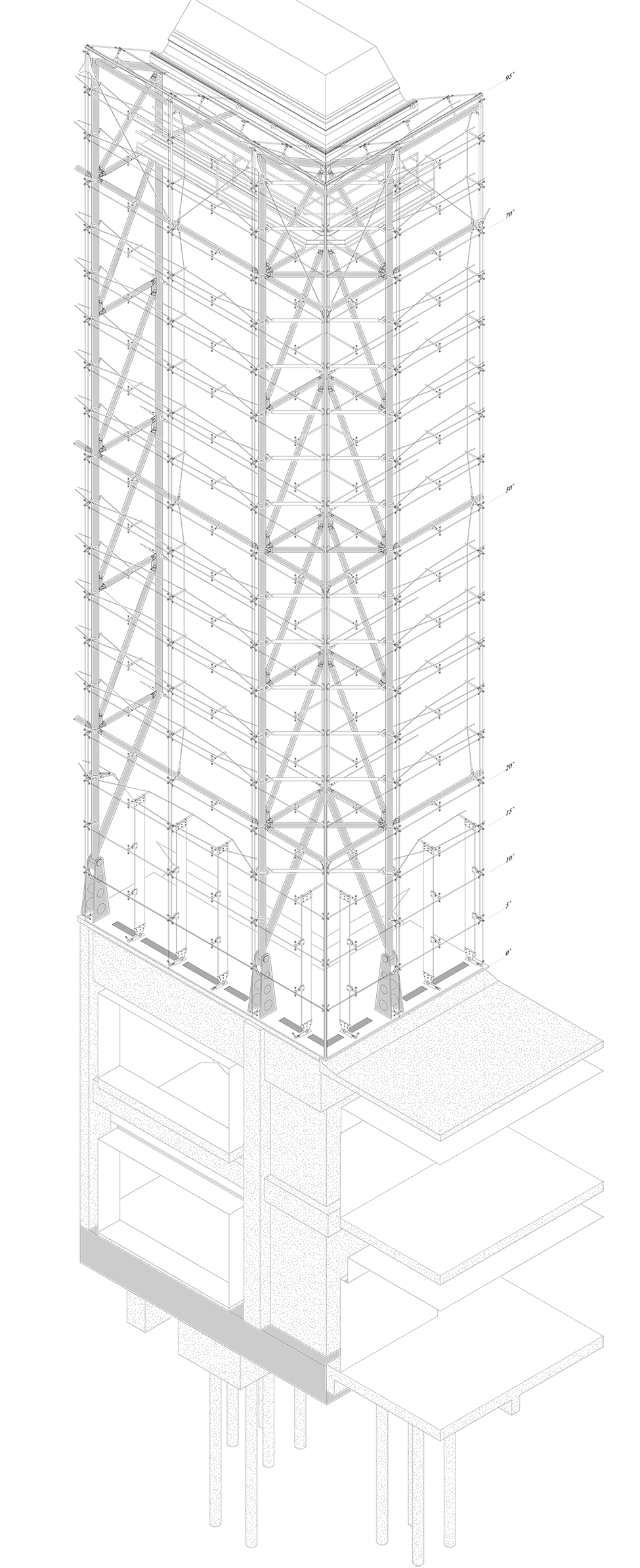
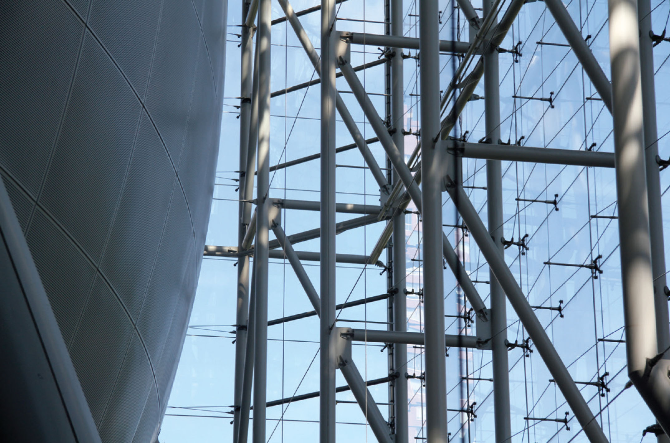
The primary building envelope for the Rose Center is a glass curtain wall that makes up the cube that houses the Planetarium Sphere. The primary aim of the facade is complete transparency, little to no light change, and consistent color during different times of day and seasons -- an effect of near dematerialization. The material choice, so-called “waterwhite” glass, was selected for its especially low iron content and the exceptional transparency that results. The surface plane is sealed with half-inch-thick translucent, weather-tight silicon joints. The facade extends from the second floor of the building, which is level with the courtyard, to the sixth floor, which is level with the existing museum structure. The curtain wall is suspended from the steel trusses that hold up the roof and transfer large lateral and vertical loads through the diaphragm and columns, as we have described in the structural paragraph. Each steel truss has a pin connection near the floor, which minimizes the amount of structure that would impede the view through the facade. There are six trusses on each side of the cube with 21’ between them. Since the trusses are built with up to an 1” tolerance and move differently under lateral loads, the glass facade must be a separate system that can be constructed, adjusted, and fl ex under lateral loads independent of the truss system that holds it up.
The glass panels are 9’ - 2 1/2” by 5’ - 0”, which means there are two panels between vertical truss support and six between each horizontal support. The glass panels rely on six spider joints to support them. At each corner of the glass, there is a four pronged spider joint that is supported by the tension rod that spans between horizontal steel truss members. In addition to the tension rod, the four pronged spider joints are attached to queen posts which are threaded together creating a vertical tension truss. On the four pronged spider joints, the upper two prongs are horizontal and stabilize the position of the glass panels while also providing lateral wind load support through a sliding mechanism. This allows the connection to slide left and right in order to be adjusted during construction and expansion of material with temperature. The lower two prongs support the gravity load of the glass panels on either side, as well as the lateral wind load. The two prongs on bottom are made at an angle of 45 degrees in order to provide the most efficient load path between the tension rod and the hanging glass. There are secondary spider joints with two prongs that are also connected to queen posts. They stabilize the position of the glass and absorb lateral wind load. The queen posts are threaded with criss-crossing cables, tightened, creating a horizontal tension truss that resists wind load between vertical steel trusses. This is the typical condition for the curtain wall system.
There are special conditions along the facade where the typical envelope structure must be enhanced because of architectural needs or various occupant needs. Near the occupied floor at the base of the facade, tension cables were not ideal because of the fear of climbing or pulling by the occupants. Therefore structural glass panels, 18” wide, were placed perpendicularly to the facade to pick up the lateral wind load. However, this system is not as strong as the typical cable system above and had to be accompanied by a customized wind load cable system that spanned between the vertical steel trusses just above the glass panels. These fixtures are larger spider joints that not only support the glass, but also have large horizontal pistons and vertically moving joints to counteract the wind load at the ground and to relieve the pressure on the glass panels.
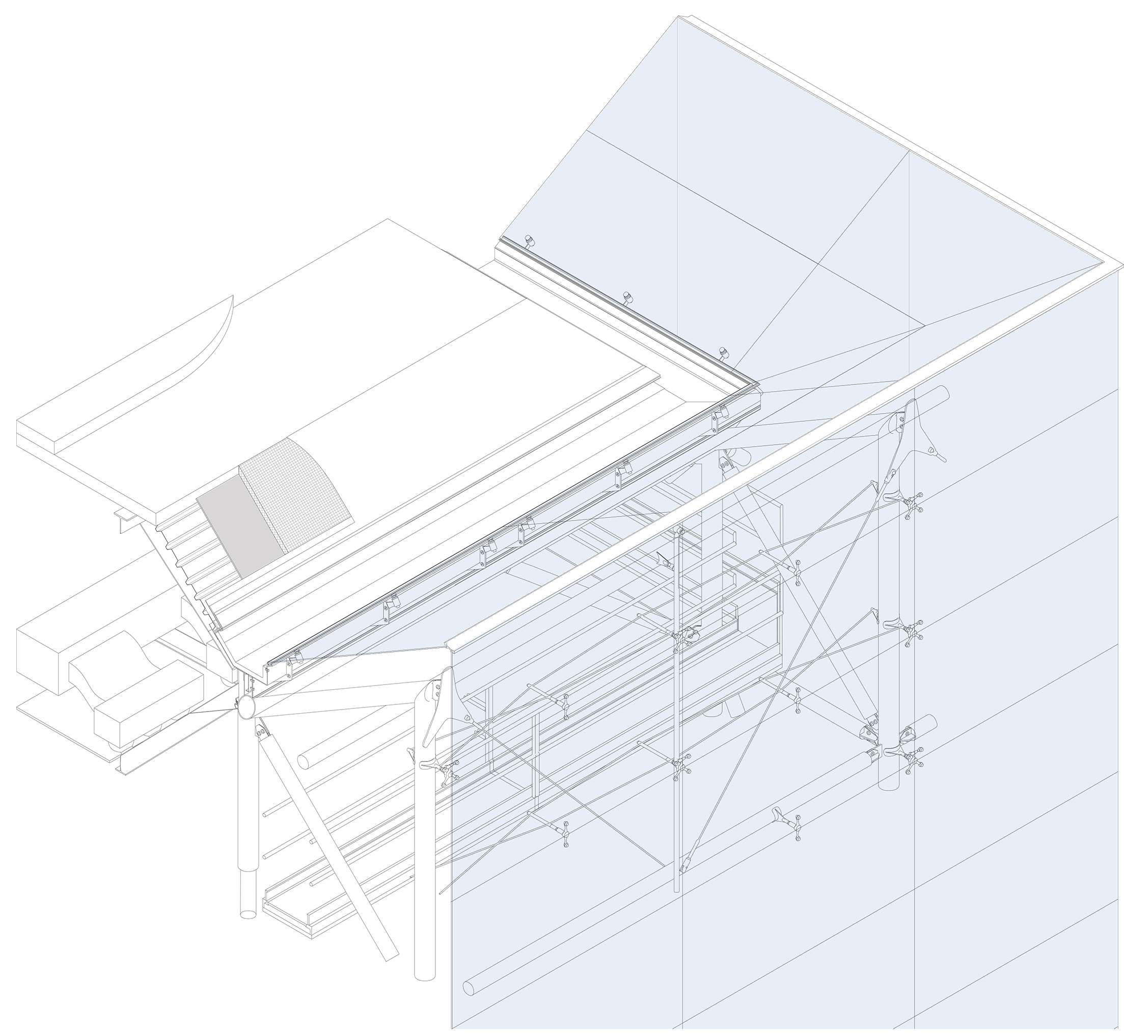
The steel trusses come together at the corner creating a completely independent rigid frame. In order to minimize the visibility of structure at the corner, smaller steel members span diagonally between the two trusses. This also supports the wishbone element (see image on right) that reaches out with two pronged spider joints to support the position and lateral wind loads on the glass panels. However, the primary support for the glass panels on the corners is a large tension rod that spans between horizontal steel truss members that extend all the way to the corner.
In order to maintain minimal structure at the roof edge that is visible on the exterior, the facade glass must turn the horizontal corner at the roof with the same architectural detail as the vertical corner on the north west side of the building. The vertical steel trusses extend to the top of the structure. However, the horizontal steel truss near the top edge of the facade is not used excessively, but rather only to support the very top edge of the glass panels and the skylight above. Therefore, in order to resist the gravity load of the three levels of glass panels at the top, there is a so-called king post suspended between diagonal tension cables fixed to the tops of the vertical trusses and is therefore in compression. A tension truss made from the queen posts hangs from the king post and supports the gravity and lateral loads of the three levels of glass panels.
There is a gutter system that guides rainwater away from the roof and building envelope. At the top of the facade, two rows of glass panes, called the skylight, are angled down to meet the gutter. The gutter has glass connectors that protrude in order to connect to the angled glass. Sealants are applied to produce a weather-sealed connection. On the roof side of the gutter, the roof, consisting of fl ashing, insulation, and metal decking, also slopes down to meet the gutter. The gutter itself is sloped just enough to guide rainwater into drains, which is then directed to the plumbing system within the building.
The construction sequence of the Rose Center for Earth and Space flows from a specific design and pragmatic logic. The first step of this process was the careful demolition of the 1935 Hayden Planetarium. It was planned and executed to enable the reuse of the 1935 piles and caps. In terms of geometry, the rigid frame and placement of trusses was designed to fit on the existing pile caps. The 1935 pile caps were fastened by a square foundational beam poured in concrete. The site was excavated to fit an additional set of pile caps supporting three other massing elements: the sphere tripod, the parking plinth, and the office volume. The new piles and caps were poured in place with concrete. Concrete columns were poured in place at the location of the parking plinth and office mass and were then fastened by concrete beams and floor slabs. Twenty four columns measuring 35 feet tall were poured in place above the square foundational beams. These columns in turn support the twenty four footings of the steel truss rigid frame.

Simultaneously, erection of the sphere began. A total of six steel legs were placed over the three foundational caps. The torsion tube beam with a 90 degree rotational tendency was brought to site and fastened to the legs. The archimedean spiral ramp was installed on site after prefabrication and torsion was complete, cantilevering from the torsion tube. The ramp is 360 feet long, wrapping helically around the lower half of the sphere and connecting the lower theater with the ground floor of the central exhibition hall. Cantilevered between five support columns by a span of 90 feet, and stabilized by contact with the sphere’s tripod of support columns and circulation bridges, the ramp’s geometry reinforces the apparent weightlessness of the sphere by carefully framing views of structural members. Its core structural element is a prefabricated torqued steel tube, thirty inches in diameter, from which an eight-foot walkway is cantilevered inward.

Following the installation of the spiral, the sphere’s circular truss plate was mounted over the legs. The plate is then welded in place. Once the three legged table was tied, a series of semi-circular rib trusses were welded to the whole. Now that the sphere had been mounted in place, construction of the rigid steel frame could begin. Pieces of the vertical truss elements were mounted over the twenty four concrete columns. As the structure was raised incrementally, horizontal truss elements were fastened to form the rigid frame. Once all the vertical trusses had been placed, the roof’s space frame was put in place. Finally, the skin could be built around the structure, starting with the roof. Spider joints were mounted on the truss, followed by glazing and steel cables that serve to fasten the facade.

'Le chêne,' pronounced [leuh-sheh-n' means oak tree in French, my native language.